Intel Pentium 4 Processor in the 478-Pin Package Thermal Design Guidelines
Design Guide
May 2002
Contents
1 Introduction ..7
1.1 References..9
1.2 Definition of Terms9
2 Thermal Mechanical Information .11
2.1 Mechanical Requirements ...11
2.1.1 Processor Package .11
2.1.2 Heatsink Attach 12
2.2 Thermal Specifications ...13
2.2.1 Processor Case Temperature and Power Dissipation ..13
2.2.2 Designing a Cooling Solution for the Intel? Pentium? 4 Processor in the
478-Pin Package ..13
2.2.2.1 Heatsink Solutions .13
2.2.2.1.1 Heatsink Design Considerations..13
2.2.2.1.2 Thermal Interface Material .15
2.2.2.1.3 Summary15
2.2.2.2 Characterizing Cooling Performance Requirements .15
2.2.2.3 Example .17
2.2.2.4 Looking at the Whole Thermal Solution17
2.3 Thermal Metrology for the Intel? Pentium? 4 Processor in the 478-Pin Package.19
2.3.1 Processor Cooling Solution Performance Assessment.19
2.3.2 Local Ambient Temperature Measurement Guidelines.19
2.3.3 Processor Case Temperature Measurement Guidelines21
2.3.3.1 Thermocouple Attachment21
2.3.3.2 Heatsink Preparation – Rectangular (Cartesian) Geometry 24
2.3.3.3 Heatsink Preparation – Radial (Cylindrical) geometry ...25
2.3.3.4 Thermal Measurement.25
2.3.4 Thermal Test Vehicle Information .26
2.3.4.1 Thermal Test Die 26
2.3.4.2 Connections .26
2.3.4.3 Thermal Measurements...27
2.3.4.4 TTV Correction Factor to the Intel? Pentium? 4 Processor in
the 478-Pin Package..28
2.4 Thermal Management Logic and Thermal Monitor Feature ..29
2.4.1 Processor Power Dissipation 29
2.4.2 Thermal Monitor Implementation 30
2.4.3 Operation and Configuration 32
2.4.4 System Considerations .33
2.4.5 Operating System and Application Software Considerations...34
2.4.6 Legacy Thermal Management Capabilities ...34
2.4.6.1 Thermal Diode .34
2.4.6.2 THERMTRIP#..35
2.4.6.3 Thermal Measurement Correlation 35
2.4.7 Cooling System Failure Warning.35 熱設(shè)計 http://www.0532yewu.com
3 Critical to Function Dimensions of Intel Reference Cooling Solution .37
3.1 Intel Validation Criteria for the Reference Design..37
3.1.1 Heatsink Performance.37
3.1.1.1 Reference Heatsink Performance Target 37
3.1.1.2 Altitude 37
3.1.1.3 Reference Heatsink Thermal Validation 38
3.1.2 Fan Performance for Active Heatsink Thermal Solution .38
3.1.3 Structural Reliability of Thermal Solution Assembly39
3.1.3.1 Test Sequence.39
3.1.3.2 Random Vibration Test Procedure.39
3.1.3.3 Shock Test Procedure .40
3.1.3.4 Post-Test Pass Criteria 40
3.1.3.5 Recommended BIOS/CPU/Memory Test Procedures...41
3.1.4 Material and Recycling Requirements41
3.1.5 Safety Requirements...42
3.2 Enabling Component Mechanical Envelope .43
3.3 Reference Solution for the Intel? Pentium? 4 Processor in the 478-Pin Package 47
3.3.1 Components 47
3.3.2 Heatsink Mechanical Design Guidelines 48
3.3.3 Reference Heatsink Attach Clip Information .50
3.3.4 Thermal Interface Material 50
3.3.5 Intel Reference Mechanical Solution Component Drawings 50
4 Conclusion51
Appendix A: Thermal Interface Management .53
Appendix B: Mechanical Drawings55
Figures
Figure 1. Processor IHS Temperature Measurement Location.13
Figure 2. Processor Thermal Resistance Relationships 16
Figure 3. Guideline Locations for Measuring Local Ambient Temperature (not to scale) .20
Figure 4. Desired Thermocouple Location 22
Figure 5. Location of Kapton* Tape for Temporary Bond...22
Figure 6. Thermocouple Bead Covered with Epoxy 23
Figure 7. Grooved Heatsink Bottom .24
Figure 8. Heatsink Bottom Groove Dimensions 24
Figure 9. Radial Heatsink Geometry 25
Figure 10. Electrical Connection for Heater...28
Figure 11. Thermal Sensor Circuit31
Figure 12. Concept for Clocks under Thermal Monitor Control.32
Figure 13. Thermal Diode Sensor Time Delay .35
Figure 14. Random Vibration PSD ...39
Figure 15. Shock Acceleration Curve 40
Figure 16. Motherboard Keep-out Footprint Definition and Height Restrictions for Enabling
Components – 1 ...44
Figure 17. Motherboard Keep-out Footprint Definition and Height Restrictions for Enabling
Components – 2 ...45
Figure 18. Volumetric Keep-in for Enabling Components ..46
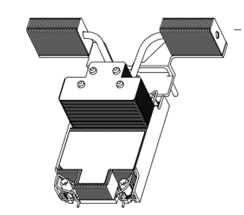
Figure 19. Exploded View of the Thermal Mechanical Enabling Assembly for the
Processor 47
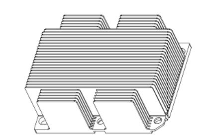
Figure 20. Heatsink, Fan, and Shroud Assembly Volumetric Keep-in49
Figure 21. Clip Bearing Surface. Critical X-Y Dimensions and Position49
Figure 22. Retention Mechanism – 156
Figure 23. Retention Mechanism – 257
Figure 24. Clip Frame..58
Figure 25. Clip Lever ...59
Figure 26. Clip Assembly60
Tables
Table 1. Recommended DC Power Supply Ratings27
Table 2. TTV Correction Factors .29
Table 3. Reference Heatsink Performance Target..37
Table 4. Fan Performance Recommendation ..38
熱設(shè)計資料下載: Intel-Pentium4Processor-in-the478-Pin-Package-Thermal-Design-Guidelines.pdf
標(biāo)簽: 點擊: 評論: